|
WELDING
SYMBOLS
Special symbols are used on a drawing to specify where
welds are to be located, the type of joint to be used, as well
as the size and amount of weld metal to be deposited in the
joint. These symbols have been standardized by the American
Welding Society (AWS). You will come into contact with these
symbols anytime you do a welding job from a set of blueprints.
You need to have a working knowledge of the basic weld symbols
and the standard location of all the elements of a welding
symbol.
A standard welding symbol (fig. 3-43) consists of a
reference line, an arrow, and a tail. The reference line
becomes the foundation of the welding symbol. It is used to
apply weld symbols, dimensions, and other data to the weld.
The arrow simply connects the reference line to the joint or
area to be welded. The direction of the arrow has no bearing
on the significance of the reference line. The tail of the
welding symbol is used only when necessary to include a
specification, process, or other reference information.
Weld Symbols
The term weld symbol refers to the symbol for a specific
type of weld. As discussed earlier, fillet, groove, surfacing,
plug, and slot are all types of welds. Basic weld symbols are
shown in figure 3-44. The weld
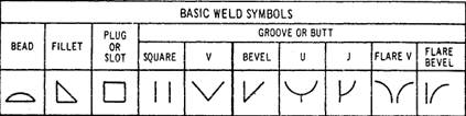
Figure 3-44.-Basic weld symbols.
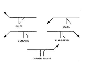
Figure 3-45.-Weld symbols applied to reference line.
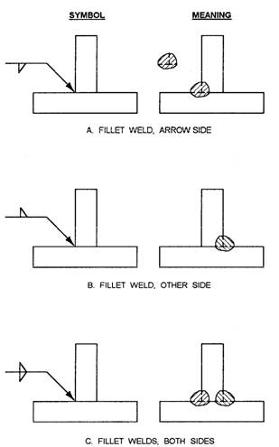
Figure 3-46.-Specifying weld locations.
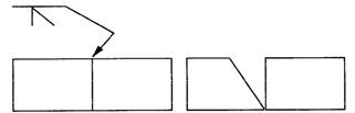
Figure 3-47.-Arrowhead indicates beveled plate.
symbol is only part of the information required in the
welding symbol. The term welding symbol refers to the total
symbol, which includes all information needed to specify the
weld(s) required.
Figure 3-45 shows how a weld symbol is applied to the
reference line. Notice that the vertical leg of the weld
symbol is shown drawn to the left of the slanted leg.
Regardless of whether the symbol is for a fillet, bevel,
J-groove, or flare-bevel weld, the vertical leg is always
drawn to the left.
Figure 3-46 shows the significance of the positions of the
weld symbols position on the reference line. In view A the
weld symbol is on the lower side of the reference line that is
termed the arrow side. View B shows a weld symbol on the upper
side of the reference line that is termed the other side. When
weld symbols are placed on both sides of the reference line,
welds must be made on both sides of the joint (view C).
When only one edge of a joint is to be beveled, it is
necessary to show which member is to be beveled. When such a
joint is specified, the arrow of the welding symbol points
with a definite break toward the member to be beveled. This is
shown in figure 3-47.
Figure 3-48 shows other elements that may be added to a
welding symbol. The information applied to the reference line
on a welding symbol is read from left to right regardless of
the direction of the arrow.
Dimensioning
In figure 3-48, notice there are designated locations for
the size, length, pitch (center-to-center spacing), groove
angle, and root opening of a weld. These locations are
determined by the side of the reference line on which the weld
symbol is placed. Figure 3-49 shows how dimensions are applied
to symbols.
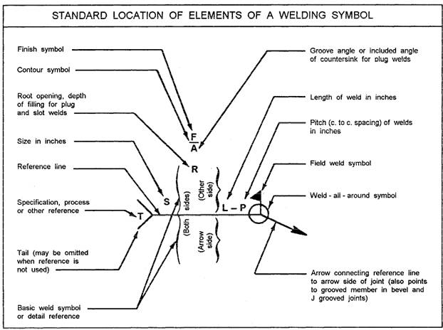
Figure 3-48.-Elements of a welding symbol.
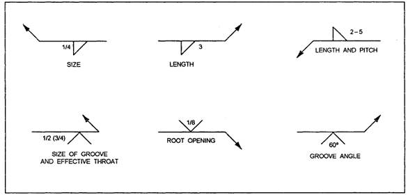
Figure 3-49.-Dimensions applied to weld symbols.
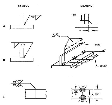
Figure 3-50.-Dimensioning of welds.
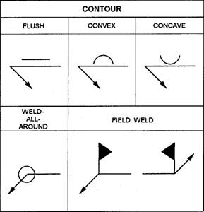
Figure 3-51.-Supplementary symbols.
Figure 3-50 shows the meaning of various welding dimension
symbols. Notice that the size of a weld is shown on the left
side of the weld symbol (fig. 3-50, view A). The length and
pitch of a fillet weld are indicated on the right side of the
weld symbol. View B shows a tee joint with 2-inch intermittent
fillet welds that are 5 inches apart, on center. The size of a
groove weld is shown in view C. Both sides are 1/2 inch, but
note that the 60-degree groove is on the other side of the
joint and the 45-degree groove is on the arrow side.
Supplementary Symbols
In addition to basic weld symbols, a set of supplementary
symbols may be added to a welding symbol. Some of the most
common supplementary symbols are shown in figure 3-51.
Contour symbols are used with weld symbols to show how the
face of the weld is to be formed. In addition to contour
symbols, finish symbols are used to indicate the method to use
for forming the contour of the weld.
When a finish symbol is used, it shows the method of
finish, not the degree of finish; for example, a C is used to
indicate finish by chipping, an M means machining, and a G
indicates grinding. Figure 3-52 shows how contour and finish
symbols are applied to a welding symbol. This figure shows
that the weld is to be ground flush. Also, notice that the
symbols are placed on the same side of the reference line as
the weld symbol.
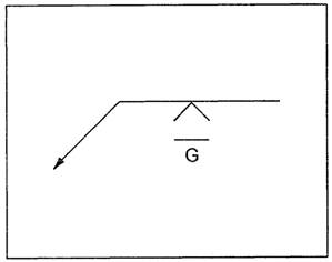
Figure 3-52.-Finish and contour symbols.
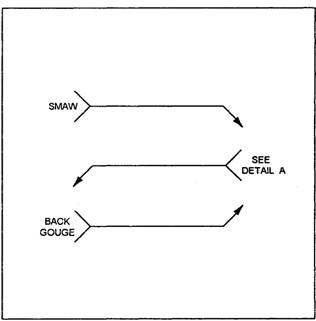
Figure 3-53.-Specifying additional welding information.
Another supplementary symbol shown in figure 3-51 is the
weld-all-around symbol. When this symbol is placed on a
welding symbol, welds are to continue all around the joint.
Welds that cannot be made in the shop are identified as
field welds. Afield weld symbol is shown in figure 3-51. This
symbol is a black flag that points toward the tail of the
welding symbol.
Specifying Additional Information
It is sometimes necessary to specify a certain welding
process, a type of electrode, or some type of reference
necessary to complete a weld. In this case, a note can be
placed in the tail of the reference line. (See

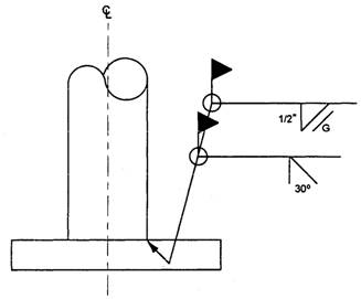
Figure 3-55.-Example of welding symbol in use.
fig. 3-53.) If additional information is not needed, then
the tail is omitted.
Multiple-Weld Symbols
When you are fabricating a metal part, there are times when
more than one type of weld is needed on the same joint; for
example, a joint may require both a bevel groove weld and a
fillet weld. Two methods of illustrating these weld symbols
are shown in figure 3-54. Note that in each welding symbol,
the bevel groove weld is to be completed first, followed by
the fillet weld.
Applying a Welding Symbol
Figure 3-55 shows an example of how a welding symbol may
appear on a drawing. This figure shows a
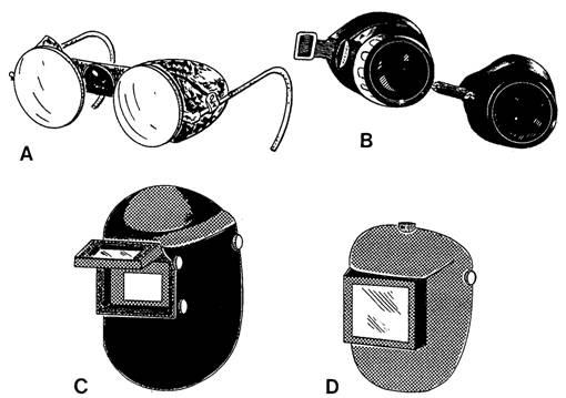
Figure 3-56.-Eye protection devices.
steel pipe column that is to be welded to a baseplate. The
symbol tells the welder that the pipe is to be beveled at a
30-degree angle followed by a bevel groove weld all around the
joint. This is followed by a 1/2-inch fillet weld that is also
welded all around the joint. Finally, finish the fillet weld
by grinding it to a flush contour. As the field weld symbol
indicates, all welds are to be accomplished in the field.
For additional information about welding symbols, refer
to Symbols for Welding and Nondestructive Testing, ANSI/AWS
A2.4-86.
Information
provided by
Tpub.com |